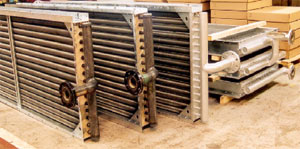
Ask The HvacMan
Air Grilles
Air Diffusers
Air Quailty
All Air Systems
All Water Systems
Boilers
Building .Managament Systems ..BMS
Burners
Chillers
Cooling Towers
Cooling Load Calculation
Cryogenics
Energy Saving
Duct
Duct ,Smacna
Dampers ,Air
Dust Collection
Fans
Fire Dampers
Glass Selection
Heating
Heat Exchangers,water
Heat Recovery
Heat Tracing Systems
Hepa Filters
Hvac Applications
Humidifiers / Dehumidifiers
Insulation , Duct
Insulation , Pipe
Insulation , Sound
Nano Tech.,In Building
Occupancy Sensors
Pneumatic Conveying
Piping
Pool Ventilation
Process Piping
Psychrometry
Pumps
Radiant Heating
Refrigerant Systems
Solar Collectors
Sound
Steam Generation
Tables & Charts Gnr.
VAV Sytems
Valves
Ventilation
VRV Systems
STORE
Solar Collectors
Flat Plate Collectors
Evacuated Tube Collectors
Concentrating Collectors
Transpired Collectors
Solar Control Systems
Standalone Systems
Grid Connected Systems
Hybrid Systems
Back-up Systems
Solar Cells
Solar Arrays
Inverters
Change Controller
Turbines
Hybrid Systems
Grid Systems
Water Pumping
Using Wind Energy
Enviromental Aspects
Buyer's Guide
 
Save Energy
Solar Water Heating
Solar Electric Systems
Wind Turbines
Passive Solar Heating
Passive Solar Cooling
Building Material
Water Conservation
Ground Source Heat-Pumps
Green Hotels

Glass &Windows Selection

 
AIR HANDLING COOLING COILS


Cooling Coil in the Main Air Handling Unit (AHU)


AHU cooling coil can use chilled water or refrigerant as direct expansion system.Chilled water temperature varies between 5-7'C.Refrigerant temperatures at direct expansion systems can be as low as 2' C.

COOLING COIL
In calculating the required cooling effect, it is
important to consider that part of the effect is
used to separate the water (latent heat) and
the remaining effect to lower the air
temperature (sensible heat). It is therefore
necessary to incorporate enthalpy differences
in the calculations to absorb the latent heat
part. The cooling effect is calculated as
follows:
Q = L . 1.2 . D h[kW], where:
L = air flow rate, [m3/s]
h = enthalpy difference for air through the coil,
[kJ/kg]


Example on calculation of cooling coil effect:
L = 1.4 m3/s
t1 = 25ºC, RH = 50%
t2 = 12ºC, RH = 100%

Enthalpy can be obtained from tables or
simply from a Mollier diagram:
h1 = 50 kJ/kg
h2 = 33 kJ/kg
Q = 1.4 . 1.2 . (50 - 33) = 28.56 kW


Google
 
Web www.iklim.com
  Discuss on the Message Board
   
 
  http://www.iklimnet.com
 
Fans
Filters
Cooling Coils
Heating Coils
Energy Saving
Humidifier
Selection Software

Manufactuer

Industry links
 
Hotels
Enviroment
Legionnare Disease
Energy Saving
Control Software
Hotel Design Books

Hotel Design