| |
 |
|
|
| |
Heat
Exchangers ,PHE
| Plate and frame heat exchangers, commonly
known as "plate" heat exchangers, originated
over 60 years ago in the European food industry. There
was a need for a heat transfer device that was energy
efficient, compact, easy to clean, and capable of being
modified as design conditions changed. These original
requirements were met with a plate and frame heat exchanger.
Introduction
Plate and frame heat exchangers, commonly known as
"plate" heat exchangers, originated over
60 years ago in the European food industry. There
was a need for a heat transfer device that was energy
efficient, compact, easy to clean, and capable of
being modified as design conditions changed. These
original requirements were met with a plate and frame
heat exchanger. Today the same fundamental needs exist
and plate heat exchangers are used worldwide in most
industries.
| |
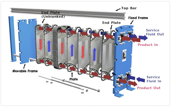
The typical components of HVAC plate heat
exchangers are:
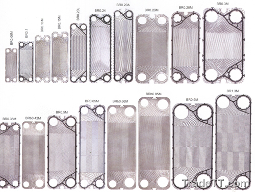
-Plates: 0.4-0.6 mm thick stainless steel
or titanium in various corrugated patterns.
-Gaskets: NBR or EPDM, for water or steam
service, respectively.
-Front and Rear Heads: Painted carbon steel
frames that hold the plate pack in compression.
-Guide Bars: Carbon steel or stainless rods
that support the plates and keep them in alignment.
-Compression Bolts: Plated steel bolts that
compress the plates and frames.
-Ports: Lap joint flanged connections or studded
ports with rubber or stainless steel liners
These components are assembled into custom
designed exchangers that have significant
advantages over shell and tube heat exchangers.
First cost is usually less due to the overall
economical design of the plate and frame heat
exchanger. Performance is superior due to
the counter-current turbulent flow that results
in high heat transfer coefficients. Higher
heat transfer coefficients require less heat
transfer surface area. Surface area is very
compact with corrugated plates. Close approach
temperatures (1-2°F) can be achieved.
Maintenance cost is reduced due to easy access
and disassembly. Installation costs are less
because of the compact size, reduced weight,
and less space requirement. There are no tube
bundles to pull and all maintenance is done
within a narrow perimeter of the unit. Designs
are flexible and can be modified after installation.
Plates can be added or removed. Various plate
patterns can be used to optimize the design
based upon heat transfer duty and pressure
drop. Single units can be designed to perform
multiple duties with three or more fluids.
|
|
| |
Design Details
Plate patterns are usually horizontal or vertical
chevrons. Horizontal patterns have more restriction
to flow which causes more turbulence, higher heat
transfer rates, and more pressure drop. Vertical patterns
have less restriction, less turbulence, and less pressure
drop. Thermal performance and pressure drop can be
optimized by using a combination of horizontal and
vertical plates (see Figure 3). Dirty liquids or streams
containing particles require a special "free-flow"
type plate with wide gaps that allow the particles
to pass through the exchanger.
|
| |
| |
The most common flow arrangement is a single
pass design that has all four connections
on the front head. This is suitable for most
applications and has the simplest piping.
For applications with low flow rates or close
approach temperatures, multiple passes are
sometimes required. Multiple pass designs
have the inlet and outlet piping on opposite
ends of the exchanger. If the inlet is in
the front, the outlet is in the rear. This
complicates the rear piping, but the addition
of a spool piece simplifies maintenance. Multiple
pass exchangers offer capital savings that
usually offset the added installation and
maintenance costs.
Approach temperature is the difference between
hot outlet minus cold inlet or hot inlet minus
cold outlet. Plate heat exchangers are capable
of 1°C approach temperatures, but the
closer the approach, the more expensive the
exchanger. It all boils down to dollars versus
degrees. Most HVAC applications are optimized
between 2-5°C.
|
|
| |
| Pressure drop is standardized at 10 psi for plate
heat exchangers. Just like approach temperature, exchangers
can be designed for 1 to 2 psi pressure drop, but they
will cost more because heat transfer surface is "wasted"
in order to accommodate the pressure drop requirement.
The best buy is generally around 10 psi drop, but some
designs fall into a smaller, more economical size with
slightly higher pressure drop. Obviously, pumps have
to be sized to accommodate the extra head pressure and
operating costs should be considered. Operating pressures
need to be specified at bid request. The effects of
operating pressure are more significant now that plates
are getting larger. Most buildings are designed for
150 psig with an ASME code rating. But the operating
systems in the building do not necessarily operate
at 150 psig. The chiller and the cooling tower probably
operate at slightly different pressures. The emphasis
is on "different." Large exchanger plates
flex in the middle and "cave in" toward
the low pressure side, creating a slightly higher
pressure drop due to the restricted flow channels.
Correspondingly, the high pressure side expands the
plate gap and pressure drop decreases. These differences
are relative to the design of the exchanger and are
typically in the 5% range; however, this can increase
with unbalanced flows. For example, if the hot side
has 2000 gpm and the cold side has 1200 gpm, the difference
is magnified. These pressure drop differences are
usually not a problem unless the pump has been designed
with minimum excess pressure. One of the good things
about a plate heat exchanger is that more plates can
be added to relieve the pressure drop. |
| |
| Operating pressures need to be specified at bid request.
The effects of operating pressure are more significant
now that plates are getting larger. Most buildings are
designed for 150 psig with an ASME code rating. But
the operating systems in the building do not necessarily
operate at 150 psig. The chiller and the cooling tower
probably operate at slightly different pressures. The
emphasis is on "different." Large exchanger
plates flex in the middle and "cave in" toward
the low pressure side, creating a slightly higher pressure
drop due to the restricted flow channels. Correspondingly,
the high pressure side expands the plate gap and pressure
drop decreases. These differences are relative to the
design of the exchanger and are typically in the 5%
range; however, this can increase with unbalanced flows.
For example, if the hot side has 2000 gpm and the cold
side has 1200 gpm, the difference is magnified. These
pressure drop differences are usually not a problem
unless the pump has been designed with minimum excess
pressure. One of the good things about a plate heat
exchanger is that more plates can be added to relieve
the pressure drop. |
| |
| Fouling factors are a carry over from the shell and
tube industry. Under TEMA (Tubular Exchanger Manu-facturers
Association) standards, a shell and tube exchanger can
be specified exactly for shell diameter; tube diameter,
length, and pitch; baffle spacing and percent cut; number
of passes; number of tubes; and tube wall thickness.
This detailed specification makes the construction and
performance of shell and tube exchangers identical for
all manufacturers. Fouling factors provide extra surface
area to accommodate partial fouling during operation.
The fouling factor is merely a percent of surface area.
This extra percentage of area is added by increasing
the tube length. The key point is "length"
of tubes, not the number of tubes. By increasing the
length of the tubes and adding another baffle, velocity
and turbulence remain unchanged and heat transfer rates
remain the same. Fouling factors work very well for
shell and tube exchangers.
Fouling factors do not have the same relevance to
plate heat exchangers because the plates cannot be
lengthened to accommodate the fouling factor percentage.
Instead of making the plates longer, more plates are
added to get the extra heat transfer surface area.
The addition of plates creates more "tubes"
or flow paths between the plates. As a result, velocity,
turbulence, and heat transfer rates are reduced. In
addition, the slower velocities sometimes promote
fouling via the settling of suspended particles. Plate
heat exchangers work best at design flow rates with
optimum surface area for the heat duty. This optimization
keeps the velocity up and allows peak performance.
If the operation changes to reduced flow rates, the
exchanger will work better if plates are removed.
Likewise, an increase in flow rate gives increased
velocity, which will generally result in higher heat
transfer rates with an increase in pressure drop.
Plates can be added as required for duty or pressure
drop. Excess surface area should be kept at a minimum
and extra frame length should be specified for future
expansion. Fouling factors should be left to the manufacturer. |
| |
| |
|
| |
|
| |
| |
|
|
|
|
|
|
|
|